QLK Float

Description
A rugged, sanitary float valve which combines quick disassembly/assembl y with easy cleaning. Sanitary finish both inside and out allows the valve to be fully submerged. The balanced plug with O-ring seals provides positive sealing. It can withstand inlet pressures up to 60 psi. It handles 100 gallons per minute at 60 psi.
FEATURES
- Easy Installation
- Rugged Construction
- Easy Cleaning and Assembly
- Smooth Open/Closing Action
- Full Flow Design
- 316 Stainless Construction
Use:
- Level Control and Overflow Prevention where very narrow variation in liquid levels are tolerated
- Throttle Flow Rates
- Reduce Pressure
- Moderate flow when discharge rate varies
- Supply low pressure, even flow rate, (foam prevention)
- General level control whenever simple maintenance, economy, avoidance of complicated devices or electrical connections are important factors
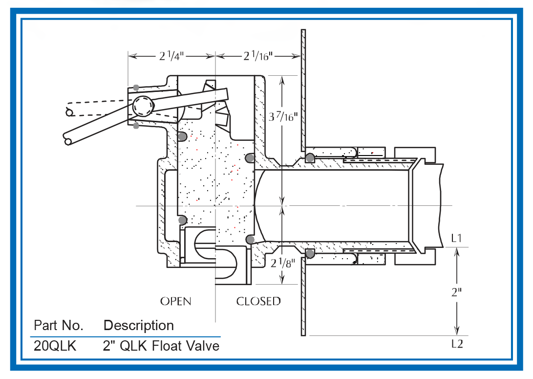
QLK FLOAT VALVE INSTALLATION INSTRUCTIONS:
- Determine the desired liquid level.
- The valve height should be located so that the maximum liquid level is between (L1) and (L2), see sketch.
- Mark wall of tank and cut hole accordingly. Weld tank sleeve (8) to the outside of the tank wall. Remove burrs.
- Insert valve body (3) with tank seal O-ring (7) in place
- Secure body to tank with lock nut (9).
- Insert float ball pivot (1) into valve body, locking with O-ring (2).
- Make sure that incoming feed line is properly supported and does not expose valve and tank wall to strain.
- Connect inlet line to valve.
- To minimize foaming, connect 21/2" Tygon tubing (customer provided) to the valve outlet, directing liquid to bottom of tank.
- Test valve in place to find liquid level necessary to open and close valve under normal operating conditions.
- Make final liquid level adjustments by bending float rod.
- Suggested O-ring supply for one year: 6 pieces of Item (2) and (7) and 12 pieces of Items (4) and (6) (see chart).
Available Options:
- Teflon coated O-rings (Items 4 & 6) where application requires more lubricity
- Viton O-rings (Items 4 & 6) where application requires higher temperatures
- Float assembly in type 316SS
- Customer specified float arm length - between 6" & 18" - 12" is standard
Notes:
- Due to varying conditions in each system, Q-Control Valves should be installed and tested in-place before being relied upon for operation.
- Information provided is general and may not apply to conditions of the individual installation
- The manufacturer’s warranty relates to workmanship, sanitary requirements, and action as tested when shipped. Any liability cannot exceed the price of the valve.
| Item | Part No. | Description | Material |
|---|---|---|---|
| 1* | QLK20FL | Float, 12" Arm + 6" Dia. Ball - Standard | 316SS |
| 2 | OR210B | O-ring | Buna-N |
| 3 | QLK20BD | Body | 316SS |
| 4** | OR326B | O-ring | Buna-N |
| OR326TC | O-ring, Plug Teflon Coated | Buna-N | |
| OR326V | O-ring | Viton | |
| 5 | QLK20PL | Plug | 316SS |
| 6** | OR325B | O-ring | Buna-N |
| OR325TC | O-ring, Teflon coated | Buna-N | |
| OR325V | O-ring | Viton | |
| 7 | OR331B | O-ring | Buna-N |
| 8 | QLK20SL | Tank Weld Sleeve | 316SS |
| 9 | QLK20LN | Lock Nut | 304SS |